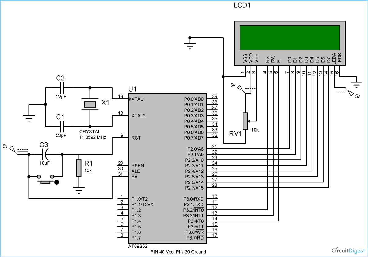

RS pin should be low to tell the LCD that the incoming byte is a command, so make it low.For initializing the LCD following commands should be given to the LCD module The first step is initializing the LCD connected by giving the command input through data line D0-D7. After holding logic 0 or logic 1 at RS pin the microcontroller should wait for specific time for LCD to process it before sending the next command or data. For sending commands the RS pin should be Logic 0 and for the data the RS Pin should be in Logic 1 or high state. The Data and the Command both are fed to the LCD through the data pins D0 to D7 but the logic state in the RS pin decides whether it is data or command given to LCD. The pin description of 16×2 LCD was given below. The Data register is for writing the data to be displayed and Command register is to write the commands. It consists of two built in registers known as Data and Command register each has a specific function to perform. The LCD display was a 16 pin package with back light, contrast adjustment and 5×7 dot resolution. It consists of 16 rows and 2 columns of 5×7 dot matrices.

This type of LCD module is very common and used widely in many types of display applications. Through this tutorial I intend to explain about programming lcd in both 4 bit and 8 bit mode with 8051 Microcontroller and programming it using Embedded C. But many times we find it difficult to interface and program the LCD properly to make it display our desired characters. Interfacing of LCD plays a significant role in wide range of digital display applications such as Voltmeter, Ammeter, Locker etc.


 0 kommentar(er)
